Project: LED Picture Box

Author’s Note
This project is a continuation of my LED Tophat project, which is not yet documented on this site. You do not need to know the details of that project to understand this one. In fact, imagine this project but in top hat form and you’ll have most of the context you need.
What to do With the Hat?
After one round of tirelessly CADing curved geometry for my LED Tophat, I was rewarded with quite possibly the coolest hat at the 2023 Odyssey of the Mind World Finals. When world finals ended, I carefully disassembled the hat for air transit. After returning home, I realized that I had no use for the hat, and the parts for the project weren’t exactly cheap. That raised the question: how can I repurpose the hardware for daily use? My answer: a cool LED box that could display what ever I wanted!
Case Design
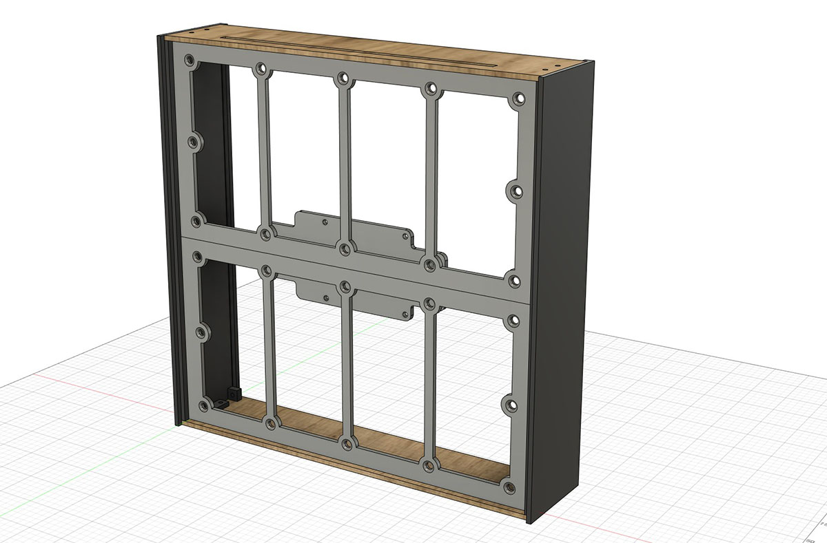
Case in Fusion 360
Going into the project, I had a few ideas for what I wanted in terms of case design. I was not sure if the box would end up on a wall or desk. I felt designing for either case was appropriate; keeping it slim and wall-mountable was a priority. In terms of aestetics, I wanted to aim for a seamless “pane of glass” design with the front face being an uninterrupted pane of frosted acryllic (I somewhat abandoned this goal). Additionally, since I enjoy laser cutting and 3D printing more than I enjoy woodworking, my design revolved around using those manufacturing tools. In essence, my design requirements were simple: make a box that’s slim, nice to look at, and easy to produce.
The design I settled on balances the simplicity of a box with complexity afforded by automated manufacuring. It is comprised of five parts:
1. Back & Bottom Panels
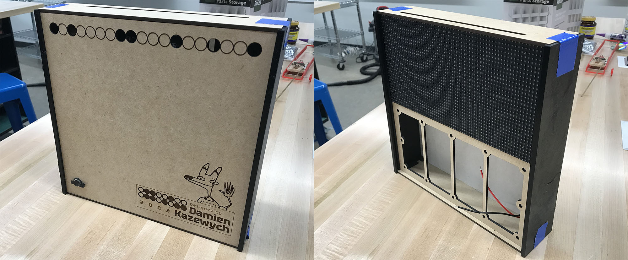
Aside from simply making them fit, there was not a lot of effort needed for the back and bottom panels. All panels have a cooling vent of some sort, and the back panel has a cool design. I could not resist engraving a little in-joke on the back.
2. Side Panels
The side panels are a crucial part of the assembly. Each side panel has tabs to help mount the bottom and back panels, and slots to hold the LED panels and frosted acryllic. The width of the side panel determine the depth of the frame. Because of the geometry of this part, I had to 3D print it, which imposed size limitations.
3. LED Panel Mounts
Designing the LED panels mounts was the easiest since I could mostly borrow the design from my hat project. The only change was that I added additional space along the vertical edge to allow it to slot into the side panels. The panels’ standoffs simply slot into the holes; screws fasten the panels to the mounts.
4. Raspberry Pi (and Mount)
Finding a good location to mount the Raspberry Pi was difficult due to size constraints. Right now, the Pi sandwiches onto the back of the led panel mounts. This works nice since none of the Pi’s I/O is obstructed. Ideally, I would have liked position the Pi so the I/O was also accessible externally: perhaps in another revision.
5. Frosted Acryllic Panel
I bought this off Amazon, so there’s not much to talk about here. I took special care to design the side panels to maintain a good spacing between the screen and acryllic. To little space would defeat the purpose of the frosted acryllic, and too much space would look blurry.
A nearly complete case assembly
Manufacturing & Assembly

A side panel being 3D printed
As I’ve already said, 3D printing and laser cutting were my weapons of choice for this project. I’ll start with 3D printing.
I decided to try printing the side panels with PETG filament since it has a higher glass transition temperature (i.e., it resists warping under heat more than PLA). I figured PETG’s thermal properties would be good in case I left the box near a window or in a car. I also learned that PETG prints adhere to smooth PEI print beds that removal of the print can destroy the bed. Naturally, I was in a time crunch and only had a smooth PEI print bed. I found that glue sticks (ironically) can be used as a release agent in a pinch. I also wiped some forehead grease on the bed for good measure. Aside from that, it was just like printing any other part.
I used a laser cutter for everything else. Previously, I would have 3D printed everything, which would have taken forever. Luckily, I had a Glowforge at my disposal. Honestly, there isn’t much to note about how I used a laser cutter. I did a little preparation on my design files, loaded them up into the software, tweaked some presets, and sent the machine to the races.
Assembling all of the parts was relatively easy. The screens fasten to their mounts with M2.5 screws and spacers. Four longer M2.5 screws are used to fasten the Pi mount to the screen assembly. I glued the front acryllic sheet to the side panels using cyanoacrylate (super glue). The screen and back panels simply slide in place. The top and bottom panels are fastened with screws. The top and bottom panels hold the screen and back panel in place.
One miscacluation on my part was how volatile superglue was. I knew supergluing an acryllic sheet to plastic could cause cosmetic issues, but I handwaved it in my rushed state. Luckily, the acryllic front panel only suffered very minor clouding. However, I made the mistake of leaving the screen installed while the glue set. I was surprised to see that a large number of LEDs had been covered with a chalky white layer, ruining their look. Fortunately, the lights were still completely functional, though I had to spend a few hours cleaning each one individually.
Software
I won’t ellaborate too much on the software design, since I go into more detail in my GitHub repository. Briefly speaking, it is written in Python (which came with some relatively large caveats). It runs on a single-threaded, coroutine-based architecture, which is just barely suitable for this application. However, I’m quite proud of how the rest turned out. There are three constructs that work together to display images: the display manager, layouts, and plugins. Without going into too much detail, the display manager decides what layout gets displayed, layouts decide what plugins get displayed and how, and plugins are responsible for generating meaningful content. For coming together in only a few days, I think it is a rather extensible system, though I think some work could be done to make it easier to understand.
Thanks for reading!